(Note dimensions quoted are usually in imperial and metric. 2.54cms = 1”inch in case we forget!)
The MAG Racing system has been developed to enable more realistic and skillful model car racing to take place in small indoor areas. To appreciate it’s great advances it it really necessary to have a permanent or semi-permanent track at table top level. The scale of the cars (1:32) is the same as slot racing and therefore tracks could be as small as a simple oval on a 36” x 48” (915 x 1220mm) base but this size would not use the potential of the system although would be useful for testing. Acceleration and braking rates have been deliberately restricted to nearer scale values for greater realism and to allow greater driving skills to be incorporated and a main straight of around 108” (2.75m) is necessary to achieve anything nearing top speed. (Remember, this is only the equivalent of 96 yds (90m) on a full size track!) Also it is good to have alternating right and left turns with racing line lane changes to test driver skills and reactions.
Magracing tracks can vary from a small home test track to a large track suitable for serious group or club racing.

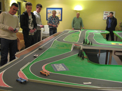
- Photo shows an early large track. Soon afterwards, reductions in guide wire diameter and improved lane change design meant the track was dismantled. In view of such developments, later tracks were somewhat smaller! Now that design has stabilised, we would happily build another track of this size.
Space Requirements
- Space available is obviously a major criterion in track design. Whatever the space available, it is desirable to fit in as much track length as possible and, if there is space, include testing driving features such as racing line routes, quick left and right bends, gradients, bridges, etc. The inclusion of a fly-over bridge does save a little space as you are getting two sections of track in one area and also provides an equal number of right and left hand turns, corners or bends. Having said this however, the ability of drivers to be able to drive back onto the track is greatly helped by having more run off area alongside the track so it is perhaps a compromise between getting as much track into the available area and at the same time having run off space outside and inside the track. Scenery, trees etc., look great but do also restrict the ability to drive back onto the track. Cars are less likely to spin and block the track than slot racing and more likely to over-steer off the track and it is helpful if there is space on the outside of the turns so that errant cars clear the track and do not block following drivers.
Many people have the idea of reproducing a full size track in miniature but frankly this is not sensible for most home or club situations. It is more important to design the track to maximise the space available and to include a variety of features. What can be done is to copy certain features from full size tracks, the Karussel hairpin at the Nurburgring for example.
Drivers Rostrum
- Whilst MAG Racing drivers can drive from anywhere around a track, we recommend that, for serious racing, the track should be designed with a view to drivers standing side by side along one side of the track as has traditionally been the case with both slot racing and R/C racing.
Driver Vision
- Fly-over bridges will inevitably block some driver vision but the track can be designed to reduce this by perhaps raising the level on the far side away from the drivers. This is always a good feature and is particularly helpful vision wise to smaller, younger drivers. A slight camber slope along the far track down towards the drivers will also help with vision.
Starting Point
- The logical start for a track design is a main straight (all tracks need at least one long straight) with the drivers in front of it. A pit lane along this straight on the outside of the track is also helpful to allow drivers to put down or pick up cars and then drive onto the track when it is clear, as full size practice. A shelf in front of the pit lane is also a nice feature for drivers to put down their transmitters whilst changing batteries for a pit stop! Unfortunately the AAA lithium-ions we are using will run for up to 30mins so pit stops are not needed very often. However, as the hobby grows, we will see endurance races and pit stops will then be a necessity.
From the driver rostrum, the best vision is in a semi circle but most tracks will probably be rectangular. A number of suggestions are shown. Tracks should be edged with a barrier to stop cars leaving the track but this does not need to be very high. 3/4” (20mm) is adequate. We use cut strips of 1/8” (3mm) hardboard pinned to the sides of the baseboard.
Lane Changes (l/cs)
- All lane changes must be designed to offer ‘straight on’ as the default (do nothing) option. Turning the steering wheel, if turned the correct way!, will result in a change of direction. If the steering is turned the wrong way, Magracing’s patented lane change plate will hold the car on the default straight on route. (Without this plate, cars turned the wrong way will leave the track and crash!)
Most tracks will contain a combination of racing line l/cs and lane change l/cs and these can often be combined.
How many lane changes?
 Whilst lane change points are easy and cheap to install, it is not necessary to have lots of them. Better to start with a few, say 4, and install extra later if it is felt that it would improve overtaking options. In practice, most overtaking comes from pressuring the car in front to make a mistake, much like full size racing!
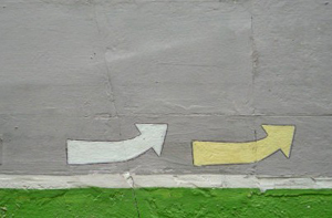
We currently have 2 tracks, Linford 4 and Linford 5 and statistically these are 65 feet (21m) length with 7 racing line options and 6 lane change options and 70 feet with 9 racing line options and 5 lane changes. Some are combined racing line and lane changes. With lap times on Linford 2 of around 12 secs, drivers have potentially up to 14 steering decisions to make every 12 secs in addition to speed control, which of course varies on each turn depending on which lane the car is in, and also decisions relating to other cars. So even a very experienced driver will need time to learn a new track. Lane change points are normally marked with arrows because, of course, it is not possible to see them. We use white arrows for racing line l/cs and yellow for lane changes and two arrows when these are combined. Position the arrows a few inches before the l/cs.
- Flyovers/Figure 8; Flyover bridges, when combined with figure 8 track layouts have the advantage of producing an equal number of left and right turns, increase the track length slightly for a given space and provide a reason for inclines and declines. They do need a little more woodworking skill however to produce the track base.
- Gradients and hills; These are no problem and add interest to any track. We have not so far had a problem with camber change or twist in the track which can occur when combining a climb with a turn but excessive twist could perhaps tend to lift the magnet and reduce steering grip.

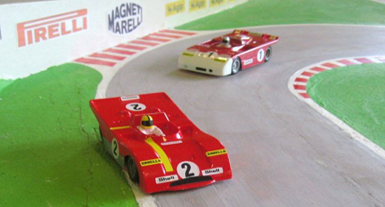
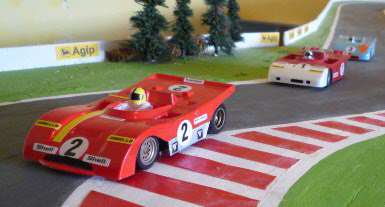
Paint the board with white emulsion and any mistakes can easily be painted out and re-drawn. Start with the main straight, draw in the turns and connect the short straights last. If the track width varies slightly, it doesn’t matter, i.e. at the exit to a turn, real cars will have two wheels on the grass. You can easily re-create this if you wish by pushing out the racing line (and the outer lane) further but still painting the track the same width or you can have cars clipping a chicane as photos.
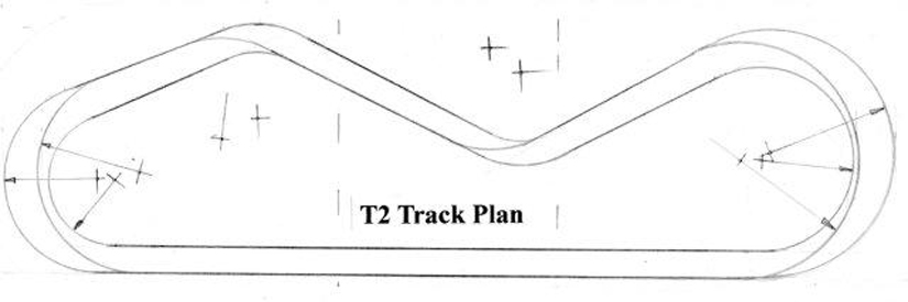
Laying out the T2 track is complicated slightly by the fact that the end turns are not 180 degrees and therefore the fulcrum points are not in a straight line so a little trial and error is required.
Re. minimum radii, we suggest around 9” (22cms)
Track Construction
- During 4 years of development, several systems of track design and construction have been tried and new ideas are still evolving. At present the simple system of marking out on a flat base, fixing the wire down with adhesive and raising the track level flush with cardboard or plaster offers maximum flexibility allied to ease of construction and low cost. We have found it difficult to rout slots to a consistent depth, especially over hills and dips in the track. Any radius curve can easily be achieved simply by flexing the wire. Spring steel wire, commonly known as piano or music wire, can be purchased in straight lengths and flexed to produce perfect curves and, if necessary for track modifications, can be lifted, cleaned and reused . Also, and very importantly, it does not easily kink and therefore can be stuck tightly to the baseboard . This is very important as the car magnet runs very closely to the track/wire and any bumps in the wire will allow the magnet to touch the wire and slow the car. 0.7mm (22swg) piano wire is the recommended thickness with 600/700 micron board used to level up.
Once the table height base has been installed, track construction is basically straightforward and requires little in the way of tools. It does require a degree of care however if cars are to race and lane change perfectly and it is probably a good idea to initially build a small test track , built perhaps in two or three sections. When this is working perfectly it could be extended. One of the advantages of the track system is that it can easily and cheaply be altered and extended. All of our own tracks have been so modified. If a curve radius proves too tight, it can easily be cut out and re-routed, additional lane changes can be added, etc..
Track Frame Construction
- Track height is usually around 28”. This could be increased at the far side away from the drivers if variations in height are incorporated and sometimes it can be easier for marshals if it is necessary to get under the track for access. Tracks can sometimes be built against a wall with a cut away section for marshalling.
You will need something like 2” (50mm) square for the legs and 4” x 1” (100 x 25mm) for the battens.
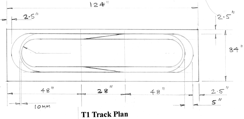
The above images show typical timber framework. The frame shown needed further cross battens to avoid the MDF sagging. Your local D.I.Y. or timber merchant will supply cut timber. Uprights and cross members are best screwed together and you will need an electric pistol drill for this. Half inch (12mm) MDF or chipboard will be thick enough if well supported . Join with timber battens, 3” wide will do the job but wider ones will keep a flatter joint. As MDF is usually available in 48 x 96 inch (1220 x 2440mm), the test track T1 shown can be made from one sheet which can be bought cut into panels for easy transport.
Cut panels from your DIY store are usually very square and, if lined up along the main straight,the edge should provide a good straight guide for the main straight wires.
Marking Out
- Pencil should mark out easily onto the baseboard and errors can be rubbed out with sand paper if necessary. A coat of white emulsion or similar paint will provide an even better surface and mistakes can be painted over!
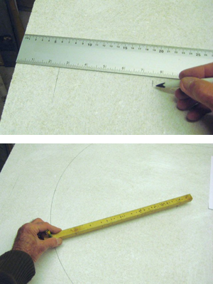
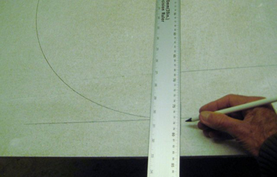
Start with the main straight. If the baseboard has a straight edge, this can be used as a guide. Having decided on the lane spacing ( 3.5” (89mm) recommended) , mark out for the two lane wires. A metal straight edge or 24/36” rule is useful here. Thes can be purchased quite cheaply nowadays. Distance from the lane wire to the edge of the track we suggest should be around 1.75” (43mm) but we usually decide this after painting the track as you may wish to vary this (on the inside of turns for example so that cars appear to run over the curb).
For marking out the curves (also known as bends or turns), a trammel is necessary (see image) This can be made from a wooden lath of around 5/8” square. Drill one hole at one end a tight fit for a pencil. Alternatively the pencil could be glued to the end. Measure along for the various radii which will be required. Hammer through a slim nail or panel pin approx. 1 ½ “ long at the selected radius.
We recommend that the outer radius of all turns where racing (fastest) line routes are used be layed out to increase the spacing between the lanes to say, for a 180 degree turn, at least 5”.
This gives greater clearance between cars to allow for tail sliding and also encourages drivers to take the racing line and penalises those who do not. (When painting the track later, the standard overall width 7” can be maintained and the offside wheels of cars on the outer lane will then appear to run wide onto the grass.)
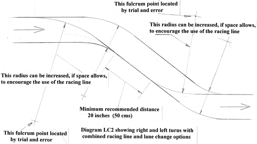
Racing lines can be installed on any curve of more than say 30 degrees but remember that the cars must be able to approach the curve on the outside lane. Also, drivers do need opportunities to overtake and gentler curves are best left with the 31/2” spacing. The racing line route can simply cut the corner and return to the outside lane or it can change from say the left hand side through a right hand curve and join the right hand lane so as to be on the outside ready for a left hand curve (see LC2) This is effectively an S bend. It is necessary to have a short straight between the LH and the RH curves to ensure that the cars are running straight at the point of the second lane change as a tail sliding car may not turn properly. Locate the position for the trammel pivot pin and tap into the base board with a hammer to mark the point. Also mark this point with a pencil X as other radii and measurements may be taken from here.

Marking the First Lane Change and First Turn
 Having drawn the 2 main straights, mark out and draw the lanes exiting the turn.
Measure from the end of the baseboard for the outer turn (say 2.5” minimum) and 5.375” further in for the inside lane (we usually allow 3/8”(9mm) between the inner and racing line wires)
Then set the trammel to the inner radius required and scribe the line. The pin can be tweaked with pliers to adjust if necessary. Set to the outer radius and scribe the outer lane lane. This same radius (for a 180 degree turn) can then be used to scribe the racing line. Make sure it blends nicely with the straight at the lane change point. For turns other than 180 degrees, most radii have to be determined by trial and error. Position the trammel pin, tap with a hammer to mark the spot, and mark out the racing line and the outer lane.
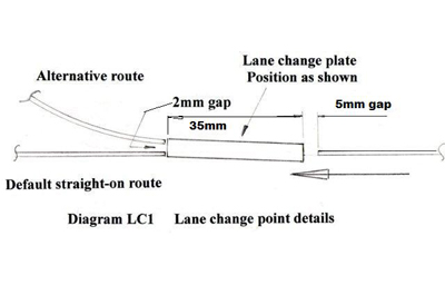
Marking out and fitting the lane changes accurately is most important if consistent lane changing is to be achieved. Measure from the end of the baseboard to the racing line fulcrum point and measure and mark this distance from the end of the baseboard at the lane change point and mark a line square across as a base line for the l/c.
Measure and mark out lines at 5mm and 40mm as shown for the lane change plate position.
Continue to work your way round the track. Adjustments will probably be necessary for more complex tracks.
Laying the Wires


- We recommend 22swg (.028”, 0.7mm) piano (Music) wire. We can supply this, also the equivalent thickness of card for building up the track level. As the flat l/c plate thickness is dependent on the wire used and the lap counter plate which fits into the track surface will be of similar thickness to the wire, using different thickness’s of wire could upset several other factors.
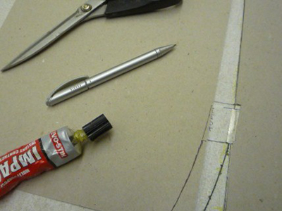
Starting with the end of the straight and the first l/c, cut the wire with side cutters or pliers to length from the base line to the join in the board, apply a run of impact adhesive along the line, lay the wire almost immediately, and, as it dries, check with a rule for straightness and adjust as necessary. Wipe the ruler clean immediately each time
Next lay the default straight-on wire.It is important that this continues in a straight line from the incoming wire. Apply glue to the short straight only and position and fix the wire checking with a ruler for straightness.


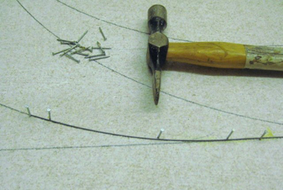
When glue has dried, curve the wire to the marked line and hold in place with small panel pins as shown. More are needed towards the end of the wire to maintain the curve. Lift the wire, apply some glue and drop the wire back in place using weights if necessary to ensure the wire sits down on the baseboard. Next apply some glue to the flat l/c plate and position immediately. Adjust carefully at an angle as shown and allow to dry.


To complete the lane change, pin and glue the alternative route wire taking care to maintain the 2mm space between the wires. Use a 2mm (.080”) drill or other gauge to check. Also ensure that the end of this wire is level with the straight-on wire. If the wires are not level, the guidance magnet will be attracted to the nearest one.
If you have ideas of modifying or extending your track in the future, it may be a good idea to butt join the wires at the joints in the baseboard. Otherwise it is not too difficult to cut the wire later if necessary using a small circular carborundum saw in a pistol or dremel drill. Ensure the joints line up exactly. Joints on a curve are a little more difficult and the wire needs holding to the curve close to the joint with extra panel pins until the adhesive has set.
You may wish to level this first section and l/c with card and test run with a car to check.
Levelling the Track with Card Panels
- The card used must be the same thickness as the wire. 600 microns, also known as 360GSM, is just under .028” but when painted is about right.
.

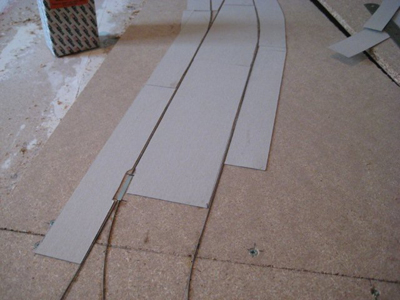
- Straight sections can be easily marked out and cut to strips with scissors. Glue to baseboard with suitable low cost impact adhesive or similar. Apply glue to the card strips, position on baseboard to transfer the glue, remove, wait a short time and bond in place. A small gap between the card and the wire can easily be filled later with filler. Ensure that the card is well stuck down. If a blister appears later, perhaps after painting, cut it out with a sharp knife, add more glue and replace.
Curved sections are a little more difficult but pressing the card down over the wire can mark it to aid cutting out. Again, the fit does not have to be perfect, gaps can easily be filled later.
It is certainly a good idea to test run and prove the track before filling and finishing just in case any alterations have to be made.
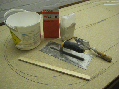
Plastering the Track
- The quickest and cheapest way to raise the track surface flush with the wire is undoubtedly with plaster or similar powder filler. It is only the quickest way if you know what you are doing however. If you have any plastering experience or know anyone who has, then this is probably the way to go. Otherwise using card panels is slower but much cleaner and simpler. Photos show a track being plastered and test run. This track is similar to the T2 track.


Finishing and Painting
- Gaps around the wire can be filled with low cost white filler and sanded down. Take care not to damage the card. After painting, the card surface will be much harder, probably better to prime paint the surface first before any filling. Any spare emulsion paint will do.
Also fill down from the card edge to the base to enable cars to run on and off the track easily. We suggest you leave filling around the lane change plates until the track has been fully tested in case any alterations are necessary. Should the card blister at any point, cut out the blister and re-stick down. Paint a wide band of white emulsion around the outer and inner track edges. Two coats may be necessary. Then measure from the guide wires and mark the track boundaries with a pencil. The guide wires can be located with a magnet if necessary. We obtain our grey track paint from our local DIY store who will mix a small sample pot of emulsion very cheaply.