Quick note before we get started
Always dry assemble a part before applying glue. This way you are confident that the part fits easily and there is no worry that the glue will dry before you have the part fully fitted. Our tolerances are tight so if you come across a tight lug is to scrape a sharp craft knife along the top and bottom surfaces of the male lug as this produces a small chamfer to help you guide the part in. Having said that, the parts are generally very accurate and we have left clearances where we can, so in most cases this isn’t necessary.
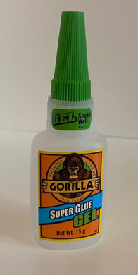
We also recommend using a super glue GEL as this helps to hold the pieces in position as they dry and doesn’t get absorbed by the MDF, however most types of glue will work and your personal preference will be fine. Usually a small amount of glue will suffice and hold the part it place.
VERY IMPORTANT, DO NOT TOUCH THE OPEN CIRCUIT BOARD WHILST IT IS SWITCHED ON. Mount the board using the sticky pad on the back so you can turn it on and off safely, and change the flash pattern between the 46 different options. The circuit board is left open to make it as small as possible for you to hide it where you want to, under the track is probably the best place for it.
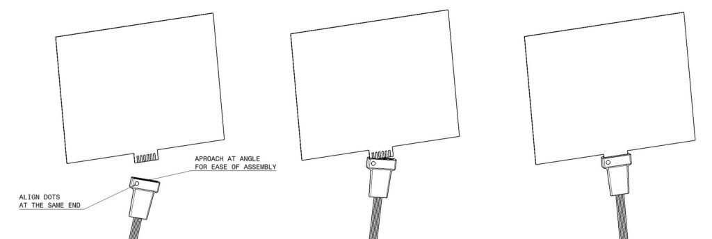
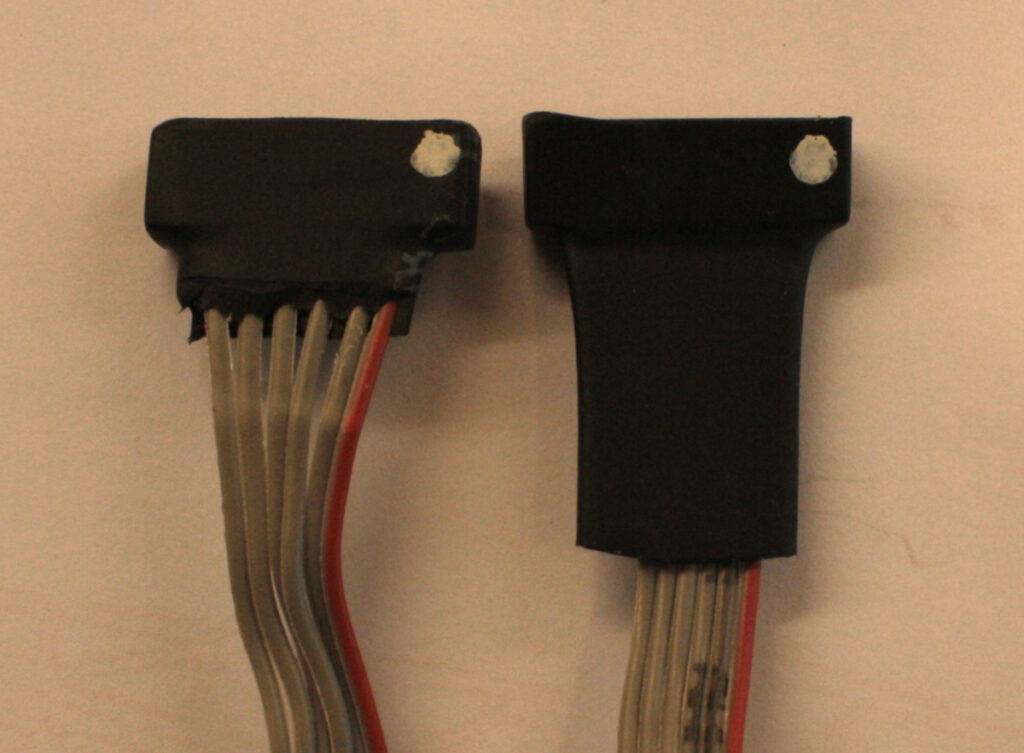
Before you assemble the billboard frame it is always best to check the function of the electronics. Connect the transformer via the cable to the display. The connector is best inserted at an angle . Make sure you have the dots on each part at the same end. (There is a second dot on the front side of the billboard display). Once connected insert 3 x 1.5v AAA batteries (Not supplied) and switch on. There is a also a button on the circuit board and this scrolls through the various flashing options. There are 46 to choose from. Do not press the button too fast otherwise the sign may not remember the one you have chosen when powered off. To obtain the desired pattern, first hold the button down until the sign goes out. Release the button and you will be at the first in the sequence of 46. Now click through the options counting as you go. Stop when you find one you like. Remember the count number, so you can easily find the one you like again should you lose where you were, The sign does remember your selection when powered off, so setting up should only need to be done once.. Some of the “Chase patterns” are more suited to the sign you have. Worn and old batteries do affect the brightness of the display.
When you are happy everything works as it should, switch off and disconnect the display.
We will now proceed to assemble the support stand. Read through the rest of the assembly guide first as there are a few tips which will help you produce a nice model without any glue showing. Also click on the images for a closer view and double check the orientation of the parts.
Assembly is best done with super glue, but if you want more working time now and again a good wood glue can be used. Also if you are not painting the structure for a wooden effect, try to place the darker sides of each part to the outsides and top of the assembly if possible. It makes the model look much nicer. We have tried where possible to produce symmetrical pairs of parts, so you should be able to achieve the desired unpainted look.
First we need to identify the parts. Some parts are quite similar looking, so here is how to identify them. Separate out the following 3 parts from the kit. They vary in size as shown. Place them on the workbench in the order shown.
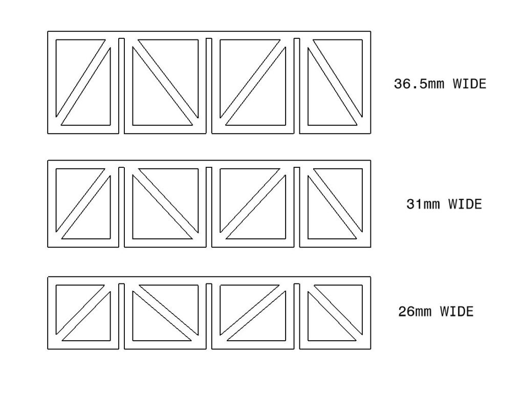
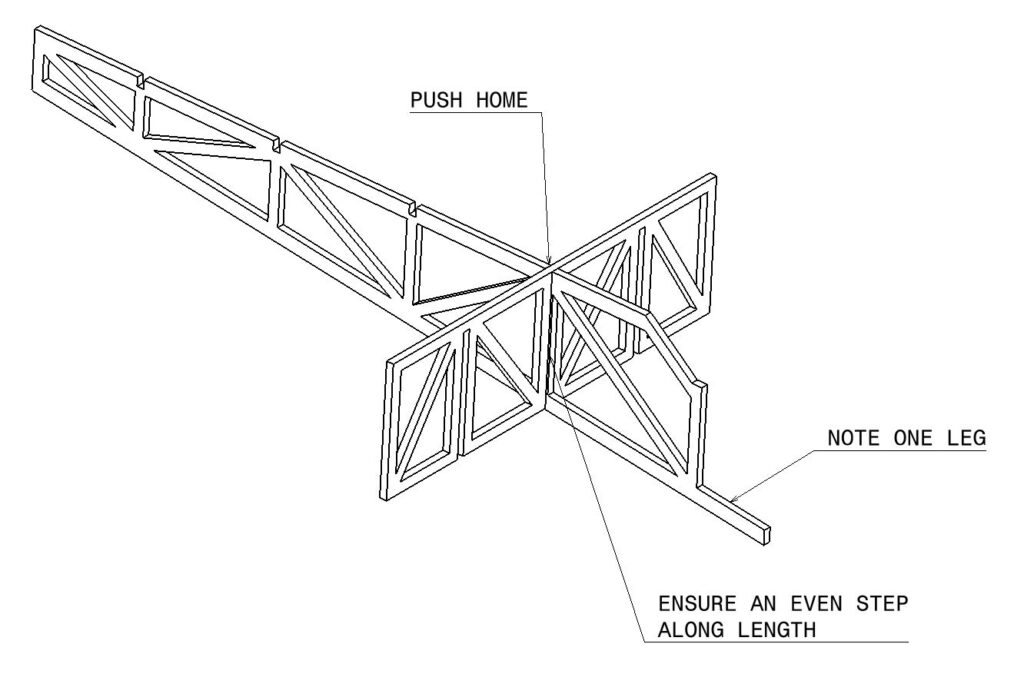
The first part we will use is the widest 36.5mm one. Take from the kit the upright which has only 1 leg at the bottom and dry assemble the two parts together as shown. Do not apply glue initially, just check the parts mate together easily. Note we are trying to assemble it so the edges align down the part as shown below. This should be quite easy to do as the notches are a good fit. Applying glue to small parts can be difficult, but the trick here is to drip a small amount of super glue on some non absorbent material such as a scrap piece of plastic. We can then use thin wire (paper clip, pin or needle) to pick up some glue and apply it accurately. We do not need much glue. Apply a drop in the bottom of one of the slots and a small drop at the lower ends of the parts. This way the glue only connects just as you slide the part fully home. It is important that you glue this in the bottom and middle slots as shown below.. Connect the parts and pinch them together to make sure the notches are fully home. Check that the cross piece runs down the centre of the strut and is not glued at an angle.
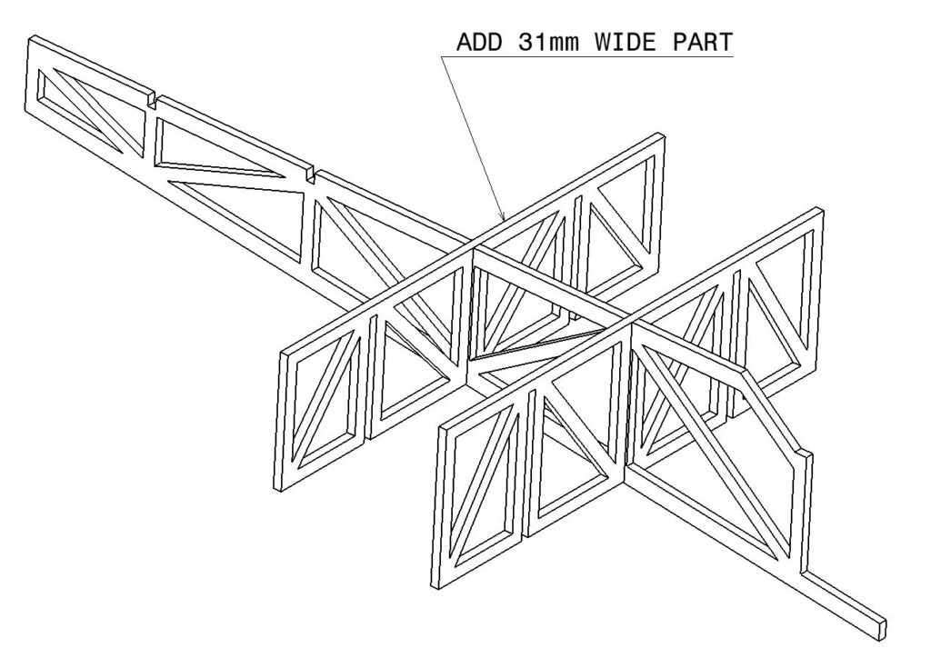
Proceed up the assembly and add on the 31mm wide part in a similar manner.
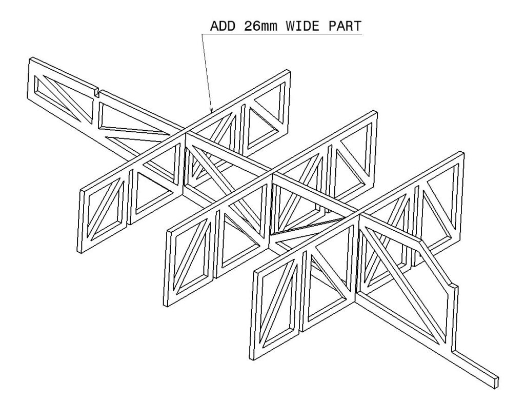
Then the 26mm wide part.
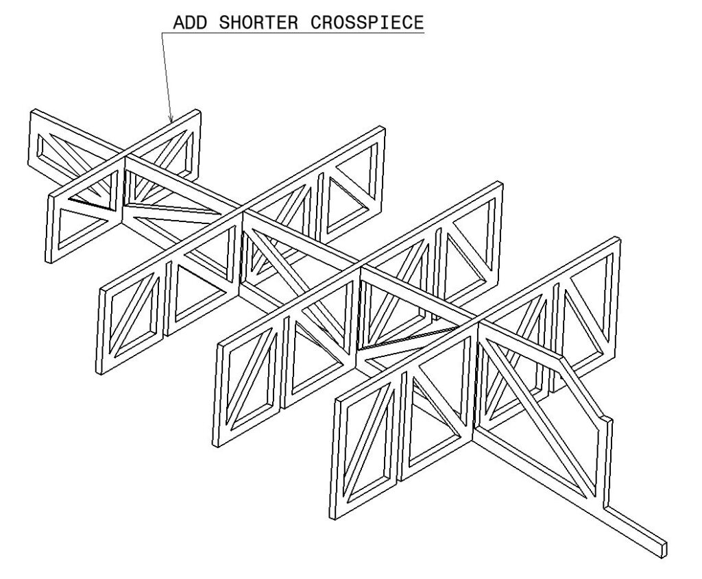
Locate the shorter crosspiece from the kit and add this to the assembly..
Turn the assembly over and locate the two longest parts that remain in the kit. Note these parts have notches which will need to go down into the slots. Also note there is a dark and light side to the parts. try to place the dark side facing outwards as if you are not painting the model it looks much nicer. Dry assemble this part so it goes together easily. Apply drops of glue in a similar manner as before but also don’t forget to add a few drops on the end of the upper crosspiece parts. IMPORTANT. Ensure there is an empty notch at the bottom of the model. it is quite easy to TRY to assemble this one notch up when you have applied glue! This isn’t actually possible, but if you are using super glue you have limited assembly time. If you are unsure, switch to a good wood glue so there is less rush.
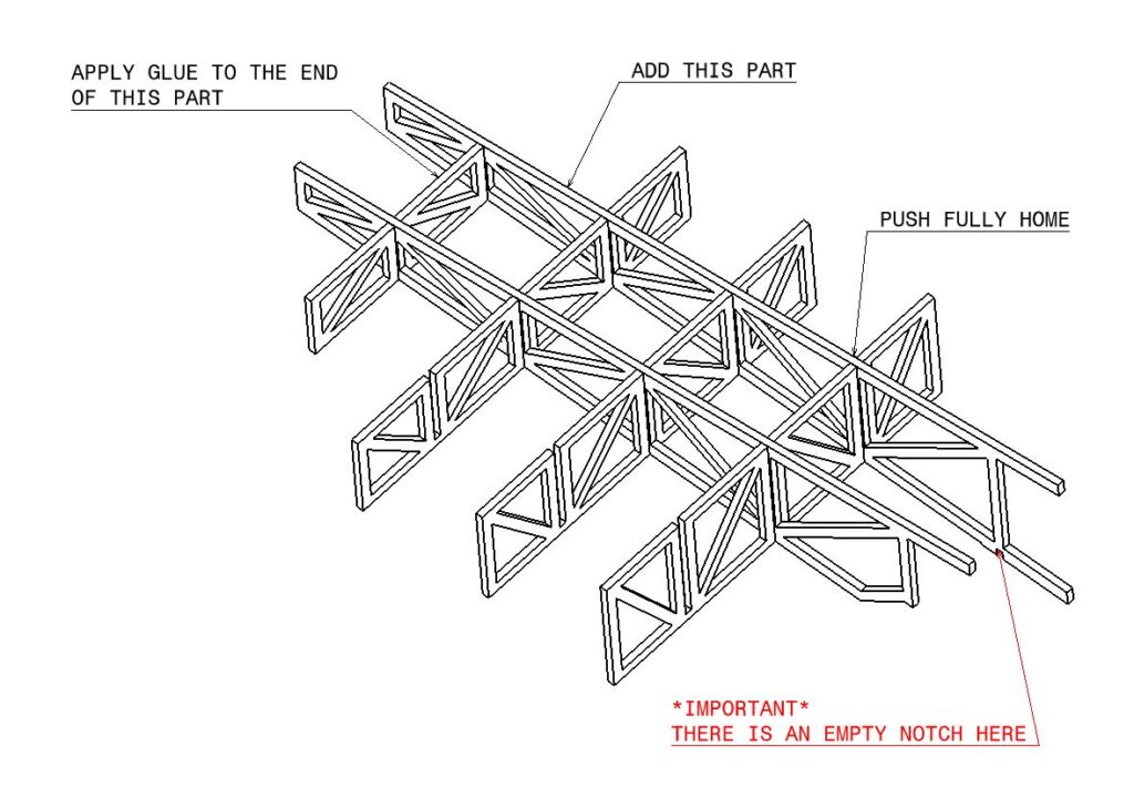
Add the second notched part in a similar manner. Once again if possible the dark side of the part should face outside

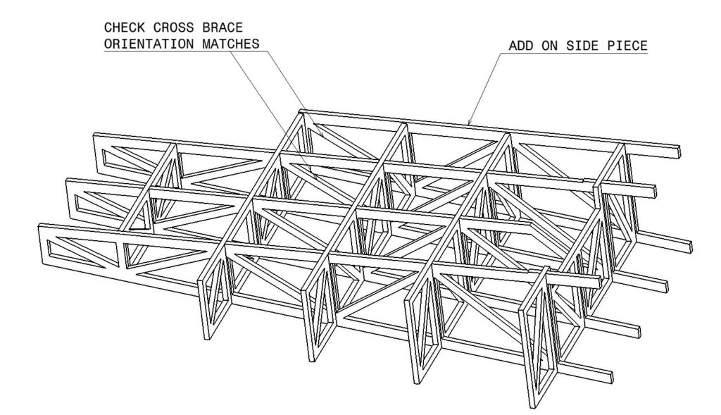
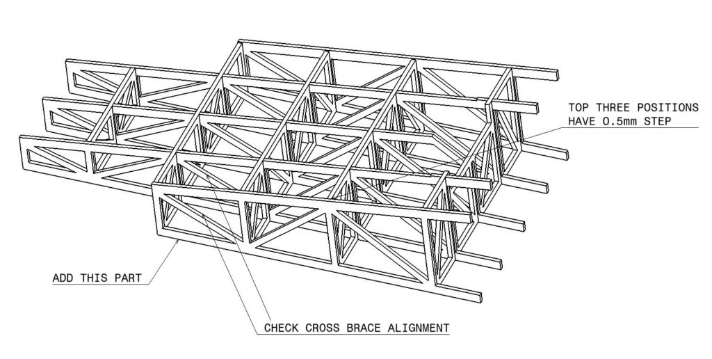
We now need to add on the end uprights. There are no notches to help here, but it is important to get these correct to make the next step much easier. Lie the model flat on its back with the missing leg upward. We are trying to achieve a small step in the first three positions as shown in the second image. This is to provide a small amount of room for the display to sit into. Check the orientation of the cross braces match the inner uprights and that the darkest side of the part faces outwards. Using the flat work surface to align the rear edges you should be able to achieve the slight steps we are looking for. The bottom cross brace is flush as shown in the second image. Once happy glue in place.
Attach the other side in a similar manner. Once again the darkest face of the part goes outside and the cross braces align with the other uprights. Again we are trying to achieve a 0.5mm step on the top three locations. Once happy apply glue and press the part together.
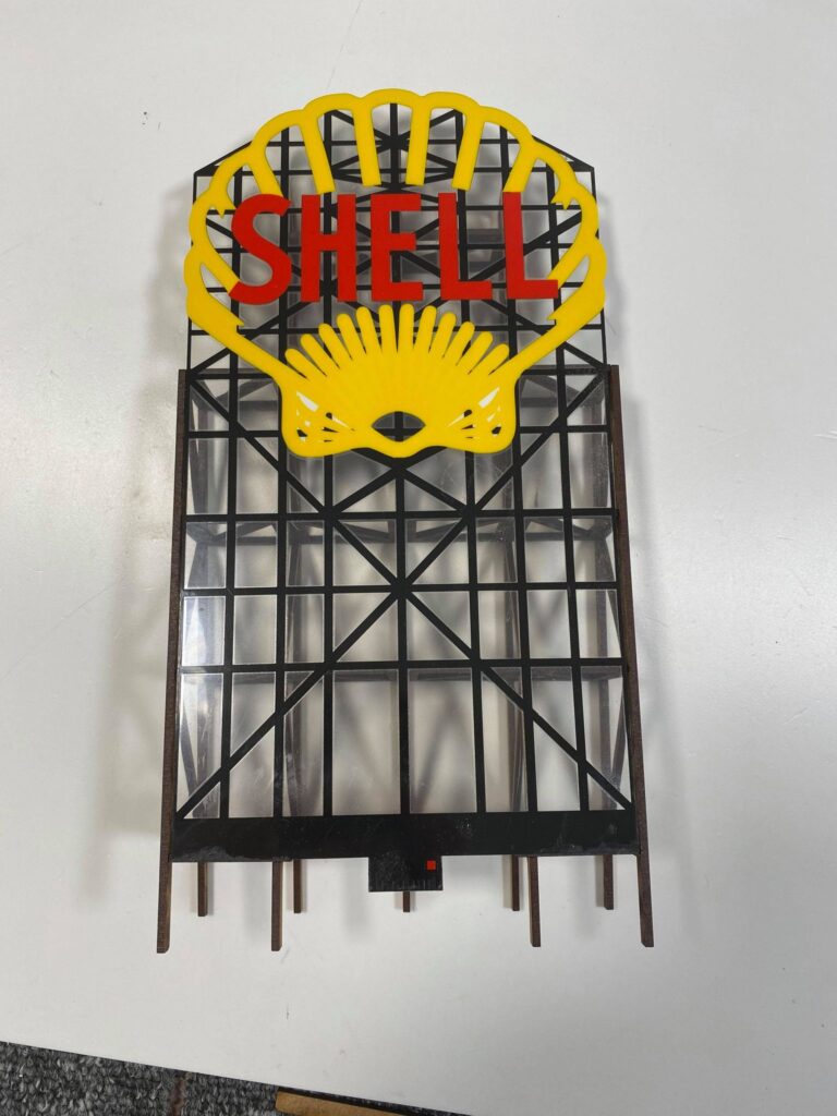
it may be possible to glue on the front wall and slide in the display module from the top, but we have found that this can prove difficult on this large model. We suggest the best way to complete the kit is to finish both the front and back sections to your desired level of finish. If you wish to paint them do them separately. Place the display sign onto the model as shown below with the logo facing upwards. The lower edge should locate on two notches. The display is very smooth and can often slide away as you are trying to finish the model, so we suggest you raise the left end of the assembly on a suitable object (Around 35mm works nicely). The display should sit naturally retained on 3 sides.
Once we are ready to glue the front panel and the flashing insert in, we need place the Shell flashing sign in the correct place. The base of the Shell sign matches up with the bottom of the frame as in this picture.
Now put glue on all the exposed bits of wooden frame, DONT PUT GLUE ON THE SHELL SIGN, especially super glue as it may frost up the clear parts of it. Use pegs to hold it together while the glue dries.
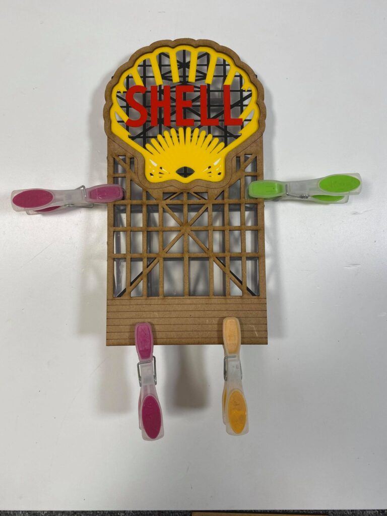
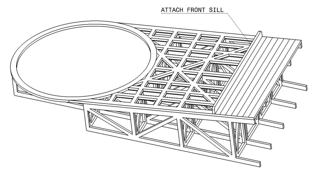
The last part in the kit is the front sill. This fits into the gap above the top etched line and the cutouts. Ensure it is square to the front face.
Attach the electrical connector. Lift the tab on the display gently with a modeling knife and slide on the connector at an angle as you did at the strt of these instructions. To hide the control board on your layout we suggest you cut a slot in the base board and attach the control board and transformer to the underside of your track. If this is not possible and you need to gain a more flexibility in the cabling this can be achieved by trimming a little of the shrink wrap from the connector. Take care not to damage the wiring otherwise your display could cease to work. This is best achieved with small nail scissors rather than a knife.
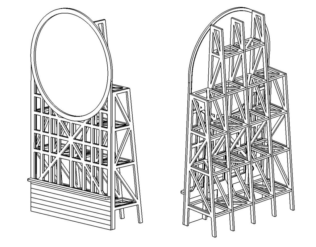
Below are some line images of how the model should look when completed. We hope you enjoyed the build.